143 lines
4.6 KiB
Markdown
143 lines
4.6 KiB
Markdown
# BH1750
|
|
|
|
[](https://travis-ci.org/claws/BH1750)<br>
|
|
|
|
This package contains an Arduino library for digital light sensor breakout boards containing the
|
|
BH1750FVI IC.
|
|
|
|
The BH1750 board uses I2C for communication which requires two pins to
|
|
communicate with the device. Configuring the I2C bus must be done in user code
|
|
(not library code). This approach has been adopted so it can be done once and
|
|
will better support the various options for different platforms.
|
|
|
|
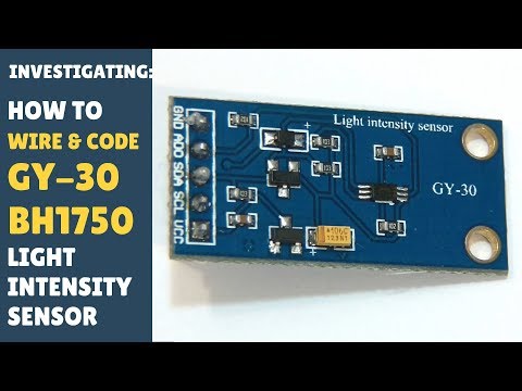
A common module containing the BH1750 component is the GY-30 shown below.
|
|
|
|

|
|
|
|
|
|
## Overview
|
|
|
|
The BH1750 has six different measurement modes which are divided in two groups;
|
|
continuous and one-time measurements. In continuous mode the sensor
|
|
continuously measures lightness value. In one-time mode, the sensor makes only
|
|
one measurement and then goes into Power Down mode.
|
|
|
|
Each mode has three different precisions:
|
|
|
|
- Low Resolution Mode - (4 lx precision, 16ms measurement time)
|
|
- High Resolution Mode - (1 lx precision, 120ms measurement time)
|
|
- High Resolution Mode 2 - (0.5 lx precision, 120ms measurement time)
|
|
|
|
By default, this library uses Continuous High Resolution Mode, but you can
|
|
change this to a different mode by passing the mode argument to
|
|
BH1750.begin().
|
|
|
|
When the One-Time mode is used your sensor will go into Power Down mode when
|
|
it completes the measurement and you've read it. When the sensor is powered up
|
|
again it returns to the default mode which means it needs to be reconfigured
|
|
back into One-Time mode. This library has been implemented to automatically
|
|
reconfigure the sensor when you next attempt a measurement so you should not
|
|
have to worry about such low level details.
|
|
|
|
The datasheet for the BH1750 chip can be obtained [here](http://www.elechouse.com/elechouse/images/product/Digital%20light%20Sensor/bh1750fvi-e.pdf)
|
|
|
|
|
|
## Installation
|
|
|
|
Click "Clone or download" -> "Download ZIP" button.
|
|
|
|
- **(For Arduino >= 1.5.x)** Use the way above, or Library Manager. Open Arduino
|
|
IDE, click `Sketch -> Include library -> Add .ZIP library ` and select the
|
|
downloaded archive.
|
|
|
|
- **(For Arduino < 1.5.x)** Extract the archive to
|
|
``<Your User Directory>/My Documents/Arduino/libraries/`` folder and rename it
|
|
to `BH1750`. Restart IDE.
|
|
|
|
The following YouTube [video](https://youtu.be/ACTMQvPVMLs) (specifically from
|
|
7:20 onwards) provides a good overview of installing this library and loading
|
|
an example using the Arduino IDE.
|
|
|
|
[](https://youtu.be/ACTMQvPVMLs?t=437)
|
|
|
|
Additional info, about library installation process - https://www.arduino.cc/en/Guide/Libraries
|
|
|
|
|
|
## Example
|
|
|
|
An example using the BH1750 library in conjunction with the GY-30 board
|
|
(which contains the BH1750 component) is presented below. The example
|
|
code uses the BH1750 library in the default continuous high precision
|
|
mode when making light measurements.
|
|
|
|
### Wiring
|
|
|
|
Connections:
|
|
|
|
- VCC -> 3V3 or 5V
|
|
- GND -> GND
|
|
- SCL -> SCL (A5 on Arduino Nano, Uno, Leonardo, etc or 21 on Mega and Due, on esp8266 free selectable)
|
|
- SDA -> SDA (A4 on Arduino Nano, Uno, Leonardo, etc or 20 on Mega and Due, on esp8266 free selectable)
|
|
- ADD -> NC/GND or VCC (see below)
|
|
|
|
The ADD pin is used to set the sensor I2C address. By default (if ADD voltage
|
|
less than 0.7 * VCC) the sensor address will be 0x23. If it has voltage
|
|
greater or equal to 0.7VCC voltage (e.g. you've connected it to VCC) the
|
|
sensor address will be 0x5C.
|
|
|
|
Wiring up the GY-30 sensor board to an Arduino is shown in the diagram below.
|
|
|
|

|
|
|
|
*The image above was created using [Fritzing](http://fritzing.org/home/) and
|
|
the GY-30 module was obtained from [here](http://omnigatherum.ca/wp/?p=6)*.
|
|
|
|
### Code
|
|
|
|
Upload the BH1750 test code to your Arduino.
|
|
|
|
``` c++
|
|
#include <Wire.h>
|
|
#include <BH1750.h>
|
|
|
|
BH1750 lightMeter;
|
|
|
|
void setup(){
|
|
|
|
Serial.begin(9600);
|
|
|
|
// Initialize the I2C bus (BH1750 library doesn't do this automatically)
|
|
// On esp8266 devices you can select SCL and SDA pins using Wire.begin(D4, D3);
|
|
Wire.begin();
|
|
|
|
lightMeter.begin();
|
|
Serial.println(F("BH1750 Test"));
|
|
|
|
}
|
|
|
|
void loop() {
|
|
|
|
uint16_t lux = lightMeter.readLightLevel();
|
|
Serial.print("Light: ");
|
|
Serial.print(lux);
|
|
Serial.println(" lx");
|
|
delay(1000);
|
|
|
|
}
|
|
```
|
|
|
|
### Output
|
|
|
|
Moving the sensor to face more light results in the lux measurements increasing.
|
|
```
|
|
BH1750 Test
|
|
Light: 70 lx
|
|
Light: 70 lx
|
|
Light: 59 lx
|
|
Light: 328 lx
|
|
Light: 333 lx
|
|
Light: 335 lx
|
|
Light: 332 lx
|
|
```
|
|
There are more examples in the examples directory.
|